In the last post, we saw that for many materials, the electric current I through a device is proportional to the voltage V applied to it, and inversely proportional its resistance, i.e. I = V/R (Ohm’s law). If there is more than one device (or resistor) in a circuit, the current through each also depends on how the resistors are connected, i.e., whether they are connected in series or in parallel.
In a series circuit (below), the resistors are connected one after the other (just as in a TV series, one watches one episode after another). The same current runs through each device since there is no alternative path or branch, i.e. I = I1 = I2. From V = IR, we see the voltage across each device will be different; in fact, the largest voltage drop will be across the largest resistance (just as the largest energy drop occurs across the largest waterfall in a river). The total voltage in a series circuit is the sum of the individual voltages, i.e. V = V1+V2. As you might expect, the total resistance (or load) of the circuit is the simply the sum of the individual resistances, R = R1 + R2.
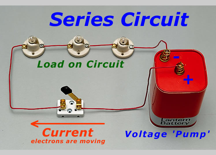
Series circuit: the current is the same in each lamp while there may be a different voltage drop across each (V = V1+V2 +V3)
On the other hand, resistors in a circuit can be connected in parallel (see below). In this case, each device is connected directly to the terminals of the voltage source and therefore experiences the same voltage (V = V1=V2). Since I = V/R , there will be a different current through each device (unless they happen to be of equal resistance) .The total current in a parallel circuit is the sum of the individual currents, i.e. I = I1+I2. A strange aspect of parallel circuits is that the total resistance of the circuit is lowered as you add in more devices (1/R = 1/r1 + 1/r2). The physical reason is that you are increasing the number of alternate paths the current can take.

Parallel circuit: the voltage is the same across each lamp but the currents may be different (I = I1+I2)
Confusing? The simple rule is that in a series circuit, the current is everywhere the same because there are no branches. On the other hand, devices connected in parallel see an identical voltage. In everyday circuits, electrical devices such as kettles, TVs and computers are connected in parallel to each other because it is safer if each device sees the same voltage source; it also turns out to be more efficient from the point of view of power consumption (an AC voltage is used, more on this later).
In the lab, circuits often contain some devices connected in series, others in parallel. In order to calculate the current through a given device, redraw the circuit with any resistors in parallel replaced with the equivalent resistance in series, and analyse the resulting series circuit.
Problem
Assuming a resistance of 100 Ohms for each of the resistors in the combination circuit above, calculate the total resistance of the circuit. If a DC voltage of 12 V is applied, calculate the current in the circuit. (Ans: 133 Ω, 0.09 A)

One thing if electrons flow from negative to positive then that would mean your very first image is incorrect by saying the way your current is flowing.
Not my diagram and it’s always shown that way for historical reasons
hey?
what battery must be used in this case?